Vibration Theory
Vibration theory is concerned with the analysis of oscillatory systems, where objects experience periodic motion around an equilibrium point. This theory covers various types of vibrations, including free and forced vibrations, and encompasses different forms such as linear and nonlinear, damped and undamped, and single or multi-degree-of-freedom systems.
Vibration analysis is applied to:
- Structural Dynamics: Aircraft wings, fuselage, turbine blades, and landing gear are designed to withstand vibrational stresses.
- Aeroelasticity: The interaction between aerodynamic forces and structural elasticity can lead to phenomena such as flutter, which must be analyzed and controlled.
- Vibration Isolation and Damping: Ensuring passenger comfort and protecting sensitive avionics from harmful vibrational frequencies during flight or launch.
- Resonance Avoidance: Avoiding resonance frequencies in aerospace structures is critical to prevent catastrophic failures.
This chapter will cover the fundamental concepts of vibrational systems, the governing equations of motion, and the analysis techniques required to model and solve vibration problems in aerospace structures.
Heads up!
Vibration theory plays a critical role in understanding the behavior of structures and materials subjected to dynamic forces. Aircraft, spacecraft, and aerospace components are constantly exposed to various vibrational loads due to aerodynamic forces, engine operations, and external disturbances. Understanding and controlling these vibrations is essential for ensuring structural integrity, improving performance, and enhancing safety.
The Harmonic Oscillator
The Harmonic Oscillator constitutes one of the most fundamental models in vibration theory. Its equations of motion in one dimension are:
where
The above equation of motion represents a spring-mass system, i.e., a mass connected to a wall via a spring.
The restoring force produced by the spring grows proportionally to
The equations of motion can be solved either using sines and cosines or a complex exponential Ansatz which we will discuss later. Using trigonometric functions for our proposed solution we have
At
which shows that the mass moves periodically about the center.
Eigenfrequencies
A 1D Harmonic Oscillator such as we discussed above has precisely one period of oscillation, and, thus, one eigenfrequency
If we differentiate our solution
On the other hand, from our equation of motion we know that
Comparing coefficients of
Dampened Harmonic Oscillator
We can use Newtonian Mechanics to study the impact of adding a damping force to a harmonic oscillator:
For linear restitution and damping proportional to velocity our equation of motion (EoM) reads
Using a complex exponential Ansatz, i.e.,
which lets us calculate the eigenfrequencies
Inserting this again into our Ansatz we find the general solution
Looking at the terms in the exponents we can define a damping timescale:
and rewrite the solution
Depending on the system this solution permits three kinds of behavior
- Underdamped (oscillatory):
- Critically damped (fastest damping):
- Overdamped (slow damping):
In order to convince ourselves that there is still some oscillatory behavior we can define
Dampened Driven Harmonic Oscillator
Even more interesting behavior can arise when a harmonic oscillator is driven through an external, periodic force
Assume
Then the equation of motion reads
This is an inhomogeneous differential equation of second order. The solution has to be found through superposition of the homogeneous and a particular solution:
It is useful to rewrite the forcing term as a complex exponential:
We are allowed to do this because
and, thus,
It is again convenient to choose a complex Ansatz since we already know this works for the homogeneous case:
We will furthermore assume that the particular solution can also be expressed in the form:
Plugging the particular solution into the equation of motion results in
so that
Calculating the complex amplitude
The particular solution, thus, reads
The total solution then reads
Resonance
Let us investigate the above soltion in more detail. Assuming
Rewriting the above equation yields
Defining the scaled amplitude
and we can equate real and imaginary parts separately, i.e.,
Squaring both equations
and adding them again gives the magnitude:
Expressing
Rewriting the previous equation for the scaled amplitude
and with
where
Finally, the phase difference between forcing and the response of the harmonic oscillator reads
These equations contain a well-known condition for resonance. If the driving frequency and the natural frequency coincide and damping is insufficient, the amplitude of the driven oscillator increases dramatically.
Coupled Harmonic Oscillators
Coupled harmonic oscillators are used as a model in several different fields to better understand energy exchange between vibrating modes in systems such as airfoils,
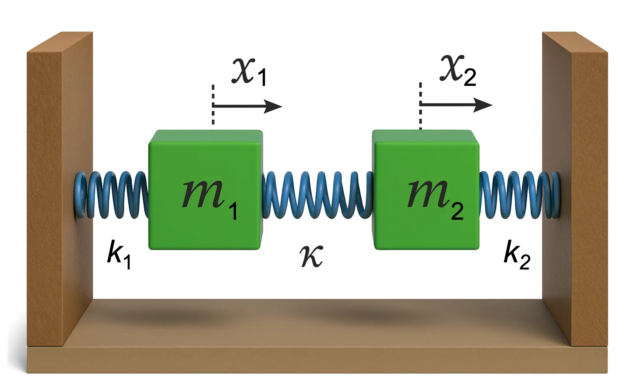
or buildings subject to external forcing. Taking the example from the lecture, we have two spring mass systems,
each coupled to its nearest wall with a spring with a coefficient

The corresponding equations of motion read
Since the coupling is linear in the states, we can rewrite that system in matrix form
where
and
This step will enable us to elegantly decouple the system by transforming into the Eigensystem of the differential equations via the (mass weighted) coupling matrix
where each component is decoupled from each other, so that
and
Using the Eigenvectors we can define a basis change matrix
Then
and
Similarly, we can find
which eventually reads
The new, decoupled Eigensystem of harmonic oscillators has the following equations of motion
Those can now be solved conveniently via our standard Ansatz
Inserting the above into the differential equations yields
With corresponding normal/Eigenfrequencies
The Eigenmode solutions then read
In order to translate the Eigenmode solutions into our original coordinates, we need the inverse of our basis transformation matrix
Example:
Let us assume the two coupled harmonic oscillators are subject to the following initial conditions
Since we already did all the work by transforming the equations of motion in
Inserting the initial conditions we find
This is a system of two equations with two unknown amplitudes
Tuned Mass Dampers
A tuned mass damper (TMD) is a device used to reduce the amplitude of mechanical vibrations. It consists of a mass, a damper, and a spring, which is tuned to a specific frequency to counteract resonant vibrations. By adding an auxiliary mass to the structure, which is tuned to a specific frequency, and connected to the main structure through a spring and a damper, the system transfers energy from the vibrating structure to the damper, reducing resonance amplitudes. Tuned mass dampers are widely used in aerospace applications to mitigate unwanted vibrations in structural systems.
Consider a single-degree-of-freedom system with mass
Now, we add a tuned mass damper with mass
Let
The damping force provided by the TMD is proportional to the relative velocity between the two masses, given by:
Heads up!
Tuned Mass Dampers (TMDs) are passive control systems designed to absorb and reduce the amplitude of mechanical vibrations. TMDs are particularly beneficial in scenarios where resonant frequencies of structures, such as aircraft wings or spacecraft components, can lead to undesirable dynamic responses. In aerospace structures, TMDs are strategically placed to address critical modes of vibration, thereby improving performance, safety, and longevity of the structure.
Tuning the TMD
The goal of tuning is to select the TMD parameters
To tune the TMD we want the natural frequency of the TMD should match the resonance frequency of the primary system:
This ensures that the TMD is tuned to the frequency where the primary system has its largest response.
The damping ratio of the TMD,
Example
Consider a system where the primary mass is
For the TMD, we select
Now, select the damping ratio
Bode Plots
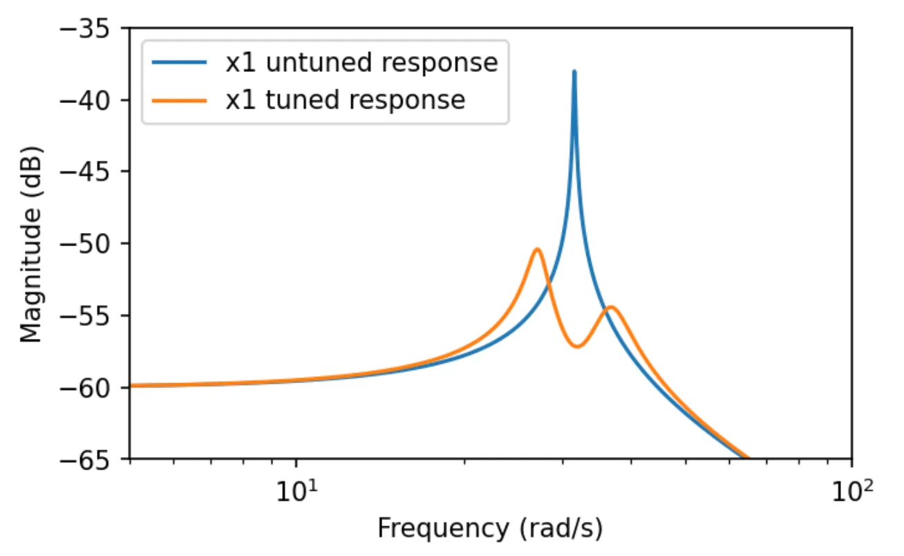
The TMD is tuned to match the resonant frequency of the primary system. Bode diagrams can be used to visually confirm the reduction in the resonant peak. The figure below shows the tuned parameter configuration from the example below. The blue curve is the frequency response without TMD, the orange one with TMD.

The figure shows that even TMDs that only weigh a fraction of the driving mass can reduce the peak amplitude by a factor of 100 (roughly -20dB power) in the vicinity of the resonance frequency!
Transfer Functions
Using the Transfer Function of a system featuring tuned mass damper is another possible way to tune TMDs.
Consider again the single-degree-of-freedom system with mass
Taking the Laplace transform yields
The transfer function
where
Taking the Laplace transform of the coupled equations (assuming zero initial conditions)
and solving for the transfer function relating the displacement
This transfer function describes the dynamic response of the primary mass when influenced by the TMD,
where again